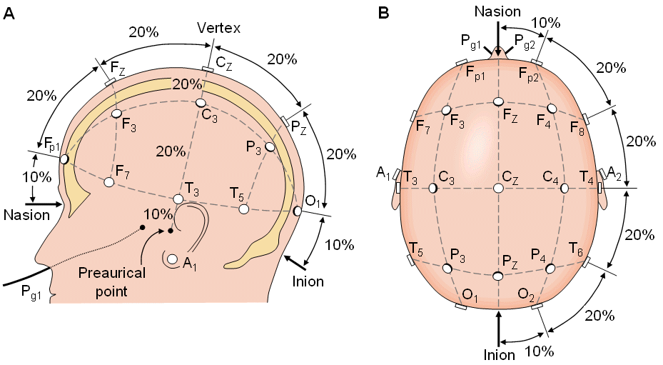
Update 9/6/12: Found for the first time, a study which equates electrode placement directly with the 10/20 positioning system. The study, Modulating activity in the motor cortex affects performance for the two hands differently depending upon which hemisphere is stimulated, was published in the European Journal of Neuroscience in 2008 and is available to download as a pdf or read in Quick View.
On each day, there was one session for anodal and one for cathodal tDCS, administered while the participants sat in an office chair. On the first day, participants also underwent one session of sham tDCS. For the anodal and cathodal sessions, 1 mA tDCS was applied for 20 min. On one of the testing days, the active electrode was positioned over the participant’s left- hemisphere motor region, centered on C3 of the 10–20 international electroencephalogram system; on the other day, the active electrode was positioned over the motor region of the right hemisphere (centered on C4 of the 10–20 electroencephalogram system). The correspon- dence between C3, C4 and the primary motor cortices of the left and right hemispheres, respectively, has been confirmed by neuroimaging studies (Homan et al., 1987; Herwig et al., 2003; Okamoto et al., 2004)
[Source of the above image is probably http://www.bem.fi/book/13/13.htm
where it’s referred to as “Location and nomenclature of the intermediate 10% electrodes, as standardized by the American Electroencephalographic Society. (Redrawn from Sharbrough, 1991).” The author seems to also have it available on ResearchGate
https://www.researchgate.net/publication/321094865_Bioelectromagnetism_13_Electroencephalography ]
While the 10/20 positioning system (wikipedia, pdf) does seem straight-forward and easy to understand, most of the electrode sites mentioned in the publications I’m reading don’t refer to it in describing where electrodes are being placed. You’re more likely to see something like: “…after bifrontal tDCS with the anode over the right and the cathode over the left dorsolateral prefrontal cortex (DLPFC).”
But if laypeople are going to be experimenting on themselves, wouldn’t they need some sort of standard reference to enable sharing of specific electrode sites? Wouldn’t you like to be able to say something like, I placed the anode over the right dorsolateral prefronal cortex at F3 and the cathode over the left at F7? In that way it would be easy for someone else to replicate. I was looking for a diagram that would map the 10/20 system over brain regions, but didn’t find exactly what I was looking for. If you have any ideas about this please share in the comments.
In the meantime here are a couple of basic brain info sites I found. These tend toward more basic information.
Healthline Brain Map
Cold Springs Harbor 3d Brain Map

